| ||||||||||||
|
©2010 AirBorn
|
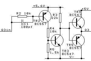
Picobus - further informationThis page expands on our basic picobus information page. There is one dual function line, Q3-, which can function as a switch to Vcc and/or as a negative supply, depending on the microprocessor motherboard implementation. No system has yet implemented this feature, however the circuit excerpt shown has been prototyped and tested.
Any circuitry utilizing the -7V rail must include a supply switch, such that -7V is only connected when +5V and Gnd are detected. Devices using -7V should also feature a prominent warning in the instructions for the user to remove power before connecting or disconnecting the Picobus connector. This page had a Maintenance update: 23 April 2013 | |||||||||||