Programmable Oscillator
|
 |
|||||||||||||||||||
| Client |
 J Dickens |
|||||||||||||||||||
| Project (Short name: progosc) |
Programmable Oscillator |
|||||||||||||||||||
| Project Status |
Design work Complete |
|||||||||||||||||||
| PCB Number |
AB0402696 |
|||||||||||||||||||
| Version Date |
24 Feb 2004 |
|||||||||||||||||||

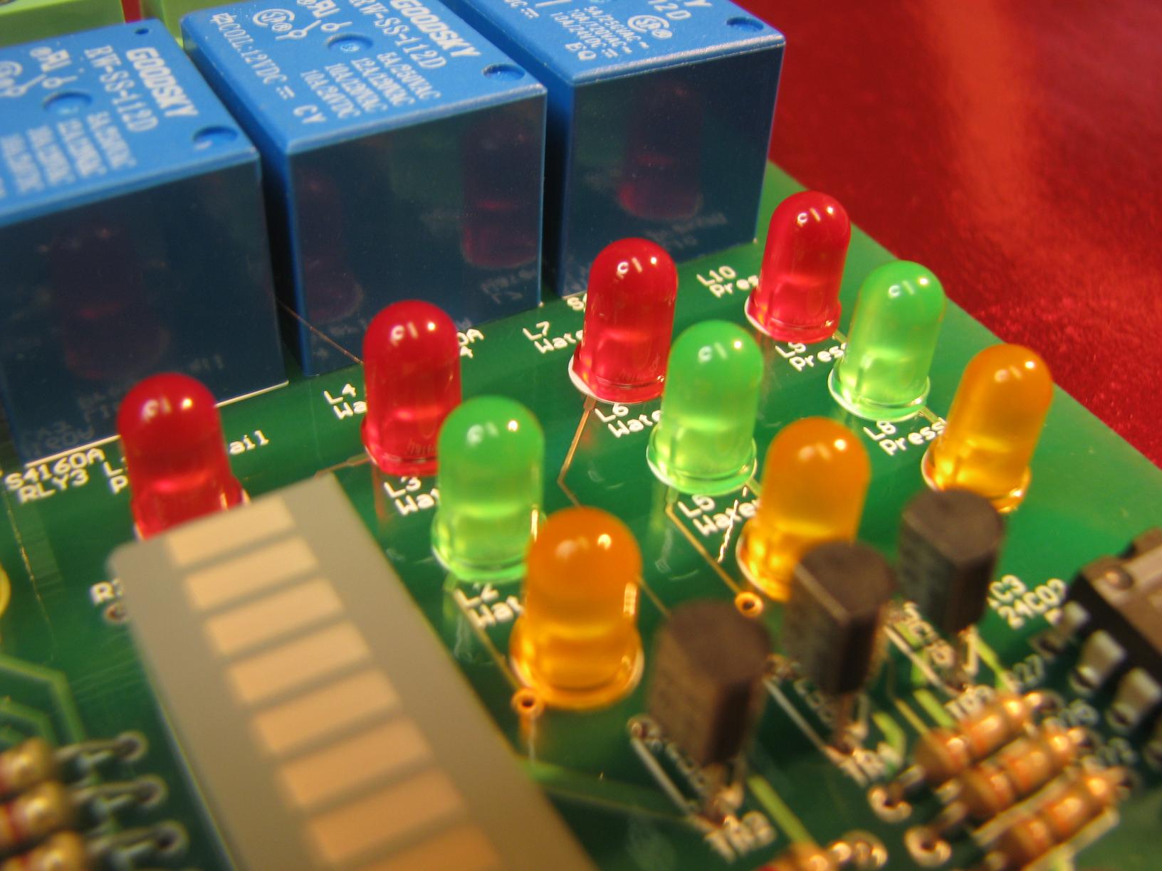
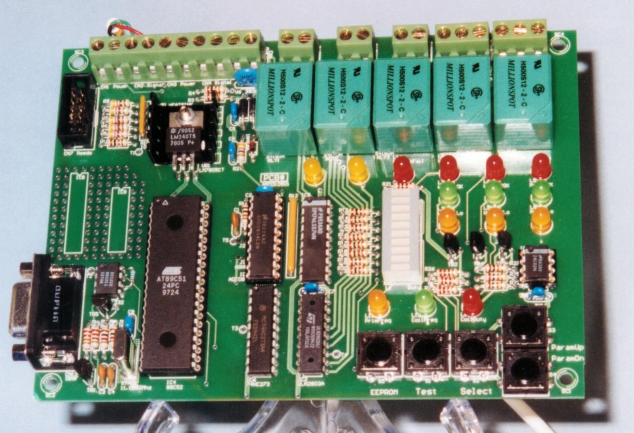
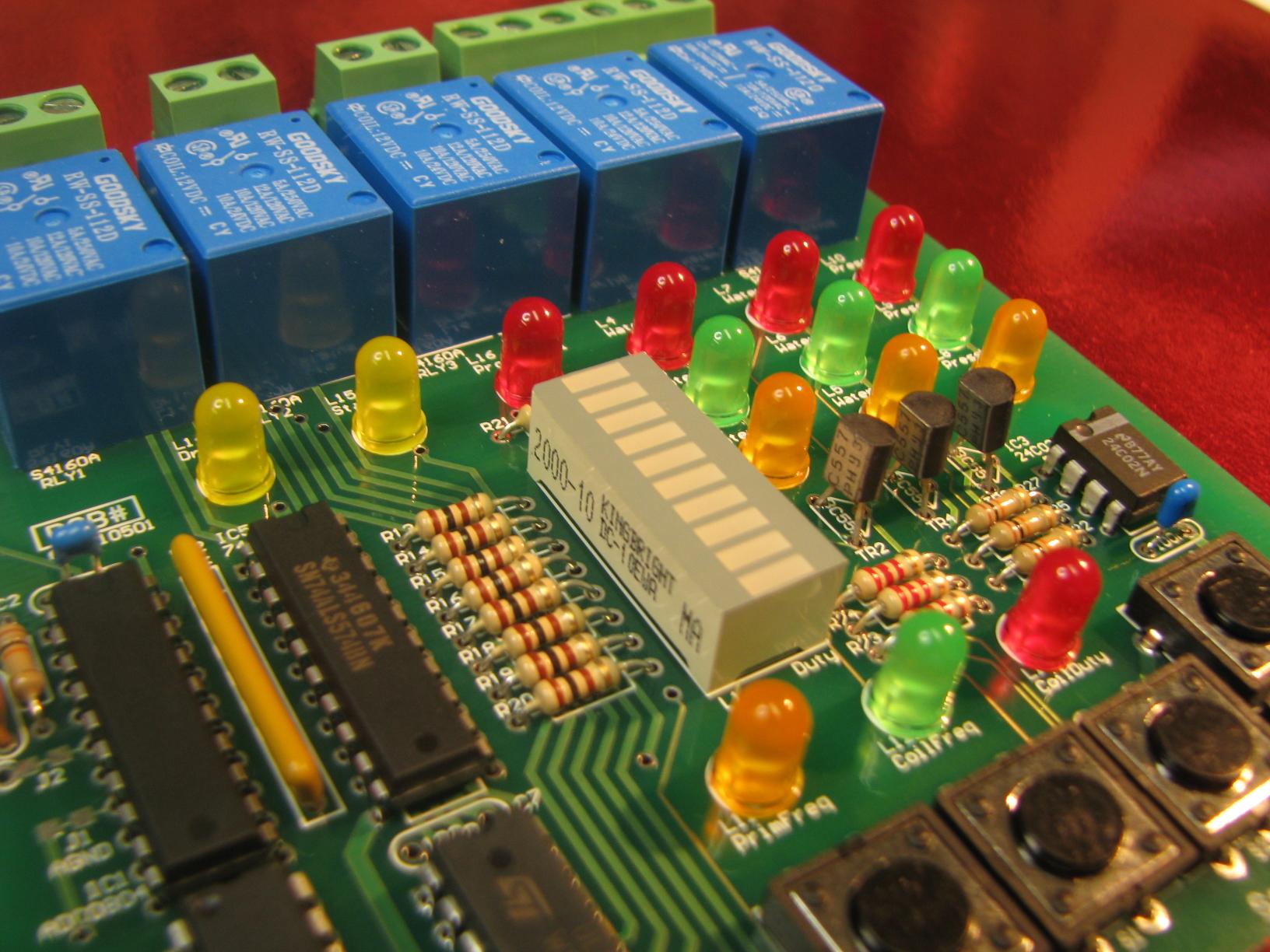
Circuit DiagramThe brief with this project was to produce cost effective electronics that could be assembled by a small, informal PCB manufacturing plant based in India, repaired easily, and producible with the minimum of setup. We used "jellybean" (common/generic/low cost) parts for this project whereever possible. While it would have reduced component count to place the A/D converter, watchdog, and EEPROM within the microprocessor, by keeping them external we could use a microprocessor that was very simple and basic, and for which very cost effective programmers were easily available. This project was all about making the board easy to manufacture with the least amount of setup and angst. The A/D receives the signal from the matching psensor pcb which conditions and amplifies the pressure sensor signal. The A/D converter we chose is a very simple part using the +5V rail as the A/D reference and providing an 8 bit parallel output which is read onto a port of the microprocessor which is coincidentally also the data bus. While the A/D converter provides an interrupt output, it is not used. A simple octal latch runs all the relays on the board, with the clock to the latch (continuously running when code is executing correctly) also feeding the watchdog circuit, and the output of the watchdog circuit also clearing the latch. In this fashion, should the code stop operating correclty, the watchdog will fire and clear the latch, clearing all the relays to the "off" state. We have a standard I/O bus that you can learn more about called Picobus. This board uses circuitry that is very similar to Picobus to multiplex the LEDs it drives, however there are sufficient outputs on the CPU to run the multiplex select lines directly, so one 4017 chip is omitted. Using an octal flip flop and 3 transistors, a total of 24 LEDs are driven, 10 of them within one bar graph LED package. The switches to operate the device are 12mm tactile push buttons assembled directly onto the PCB, and directly input to the microprocessor port pins taking advantage of the internal pullups within the CPU itself. The power supply is simple, with VDR overvoltage protection and two reverse polarity diodes. VDR protection was added to the relay contact outputs to prevent inductive back emf problems. A very simple serial circuit was integrated onto the PCB - it was not intended for high speed or long distance operation, it just uses two transistors as the drive elements and does not swing to full RS232 compliant voltage levels.
|
||||||||||||||||||||
Bill of materials
Parts list and notes |
Programmable Oscillator Bill Of Materials |
|||||||||||||||||||

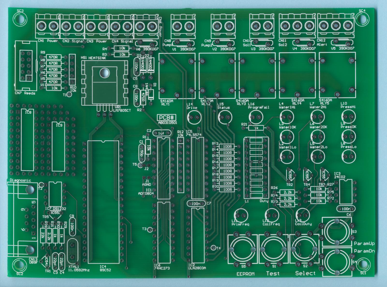
PCB design
This board layout was deliberately kept simple, open and robust. 12 thou x 12 thou design rules were used, but often the tracks were made larger than required just because they could be, and it helps in production. The majority of wiring connectors were kept along one edge. This project has emphasised low unit price and keep-it-simple engineering, so the wiring blocks used were plain 5mm type without plug / unplug capability - cheap but effective. The reeds were connected using ribbon cable as this is a very cost effective way to do simple field wiring - at one end the IDC10 connector is crimped on, then at the other end the ribbon is stripped back and soldered permanently to each of the reed switches. The serial is a standard DE9. There is a prototyping area at one side of the board, but all up the design is fairly compact for a Thru-hole board. |
||||||||||||||||||||
Gerber files
The PCB manufacturing files |
Programmable Oscillator Gerber files |
|||||||||||||||||||
Final board |
 |
|||||||||||||||||||
 |
||||||||||||||||||||
 |
||||||||||||||||||||
Documentation package |
Programmable Oscillator Documentation (PDF) |
|||||||||||||||||||
| Copyright |
©2010 AirBorn Electronics Pty Ltd |
|||||||||||||||||||
- Contact Us
- Enquiry Form
- Sitemap
- Our Design method
- Spec'ing your job
- Hardware design
- Firmware design
- Examples: Circuits
- Examples: Photos
- Index of Client PCBs
- This page on website
- Our Circuit Library
- Serial to Parallel
- Navy SMD Trainer
- Danfoss tester
- 89C2051 project
- Weighscale
- Light Key
- Tone Gen
- Design step-by-step
- Circuit diagrams
- PCB Layout
- PCB Etching
- Prototyping
- Firmware design
- Documentation
- Manufacturing
- Economies of scale
- Test Procedures
- ECOs - changes
- Project Specifications
- Specification Intro.
- Writing a Spec
- Tech Ingredients
- Example Specs
- Engineer employment
- R&D Economics
- Design Inspiration
- Example projects
- ...more
- ...more
- A PCB Factory
- A real design Lab
- Our PicoBus IO Std
- RS232 RS485
- FR4
- Autotrax
- CAD Library
- P89LPC932
- Program Header
- Past products
- Using a Multimeter
- Complete site index
- Offsite Links (15000+)
- Google search
- Contact
©2010 AirBorn - Last updated 08 July 2010
Background Image Credit: IC 1396 H-Alpha Close-Up : Nick Wright (University College London), IPHAS Collaboration