RS232 connections, and wiring up serial ports
| Pin 1 | Protective Ground | |
| Pin 2 | Transmit Data | |
| Pin 3 | Received Data | |
| Pin 4 | Request To Send | |
| Pin 5 | Clear To Send | |
| Pin 6 | Data Set Ready | |
| Pin 7 | Signal Ground |
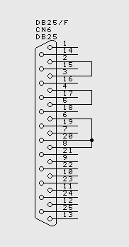
![[DB25/F loopback wired]](db25wiredfront.jpg)
|
| Pin 8 | Received Line Signal Detector (Data Carrier Detect) | |
| Pin 20 | Data Terminal Ready | |
| Pin 22 | Ring Indicator |
The connector on the PC has male pins, therefore the mating
cable needs to terminate in a DB25/F (Female pin) connector.
| Pin 1 | Received Line Signal Detector (Data Carrier Detect) |
![[DE9/F loopback wired]](de9wiredfront.jpg) |
| Pin 2 | Received Data | |
| Pin 3 | Transmit Data | |
| Pin 4 | Data Terminal Ready | |
| Pin 5 | Signal Ground | |
| Pin 6 | Data Set Ready | |
| Pin 7 | Request To Send | |
| Pin 8 | Clear To Send | |
| Pin 9 | Ring Indicator |
The connector on the PC has male pins, therefore the mating
cable needs to terminate in a DE9/F (Female pin) connector.
[Some people call this a DB9... DE9 is the real name, however]
Wiring up something nice and simple, for instance a plain old "dumb terminal", is just a matter of connecting Tx, Rx and Ground, right?
Usually Not. While the normal PC hardware might well run with just Tx, Rx and Ground connected, most driver software will wait forever for one of the handshaking lines to go to the correct level. Depending on the signal state it might sometimes work, other times it might not. The reliable solution is to loop back the handshake lines if they are not used. We specifically chose to use the Personal Computer (PC) as the frame of reference for the signals on this page. RS232 predates the PC, but even with EIA-574 and the later TIA-232-F the definitions still use DTE (Data terminal equipment - such as a PC or equivalent) and DCE (Data circuit-terminating equipment - such as a modem or 'dumb terminal' or any other device) as the frame of reference. We are trying to flatten the learning curve: On this page "PC" is used in place of the technical term "DTE".
|
| ||
|
![[DE9/F loopback wired]](de9wiredbacka.jpg) |
![[DE9/F loopback wired]](de9wiredbackb.jpg) |
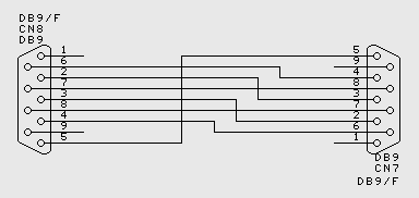
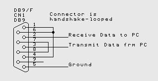 Handshake looping a PC serial connector
When the lines are handshake looped, the RTS output from the PC immediately activates the CTS input - so the PC effectively controls its own handshaking... which leads in to what each of the pins on the RS232 connector (or EIA574 in the case of the DE9) actually does - we have a proper description of all the pins further down this page.
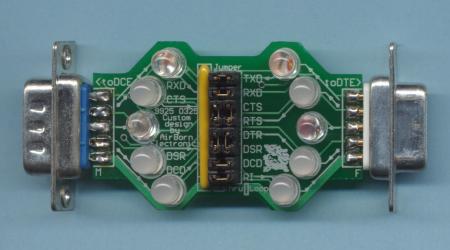
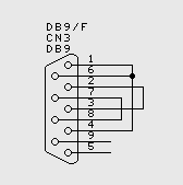 RS232 DE9 PC Loopback test plug Build it yourself using the photo to the right as a guide - or if you prefer we will do it for you: $18 + shipping |
![[DE9/F loopback plug]](de9loopback.jpg) |
|
The PC loopback plug is a useful diagnostic tool. The loopback plug connects serial inputs to serial outputs so that the port may be tested. There is more than one way to wire up a loopback plug - but this is the most common. | |
|
|
![[DB25/F loopback plug]](db25loopback.jpg)
|
Connecting together two serial devices involves connecting the Rx of one device to the Tx of the other, and vice versa. The diagram below indicates how you would go about connecting two PC's together, without handshaking.
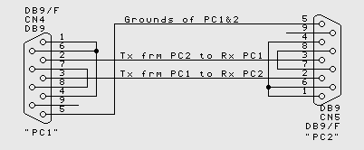
Connecting two PCs together using RS232, without handshaking
When Handshaking is required, generally RTS of one device connects to CTS of the other, and vice versa, and also DSR of one device connects to DTR of the other device, and vice versa. The particular requirements for different equipment may vary.
Connecting two PCs together using RS232, with handshaking
Using a Breakout box or LED box to work out cabling
If you have problem with RS232 cabling, your best "emergency" tool may be a breakout box (sometimes called an LED box). The normal units only come in the DB25 size, but with a couple of DB9 to DB25 adaptors, they can be used with DB9 cables as well. The units have an LED for each signal line in the cable, and the LED lights green or red dependent on the signal state. Our D9 Breakout box is a little more sophisticated - it also allows you to disconnect certain lines in the cable, and to loop signals to their opposite number - good for trying new cable wiring possibilities.
The first thing to remember, is that there is a good chance the two devices you are trying together will actually work if you can get the cable correct. If you have some other way to actually prove this - for instance by trying each of the devices on another system - do it.
Given a hypothetical example - for instance connecting a standard PC with a DE9M to
 an CNC industrial turret punch, also with a DE9M, the first thing I would try and do
is get a cable that I think would work.
In this instance, I would either purchase or build a null-modem cable (DB9F to DB9F) -
actually, I would copy the last example, basically the cable used to connect two PCs
together with handshaking.
an CNC industrial turret punch, also with a DE9M, the first thing I would try and do
is get a cable that I think would work.
In this instance, I would either purchase or build a null-modem cable (DB9F to DB9F) -
actually, I would copy the last example, basically the cable used to connect two PCs
together with handshaking.
Given the cable that I believe will work, connect the cable, LED box and two devices all together. Before powering on both devices, unplug just one of them. Power the devices on and make a note of which LEDs are lit. Then unplug the connected device and plug in the disconnected one, without rearranging the cabling otherwise. Again make a note of which LEDs are lit. If any single LED is lit by both of the devices, then there is an output conflict, and the cable wiring is incorrect. By this, I mean that one line in the cable has an output driving it from both ends - and this is not correct for RS232 - so that means that the cable wiring is not correct for the devices. Pay particular attention to Tx and Rx.
To continue with the example above, if I saw that two ends were driving the same lines, I would assume the null modem cable was not correct, and I would try a one-for-one (or "straight-thru" DE9F-DE9M cable) with a gender changer (DE9F-DE9F in this instance) instead.
If each end drives its own set of LEDs, connect the two ends together. In normal situations, you should see all the LEDs light up - but there are some devices which will not light up all the LEDs. Having said that, if one of the devices is a PC and any LED except RI (Ring indicator) is not lit up, the cable will probably not work.
Normally, other cabling problems will involve handshake lines. An LED box will be an invaluable guide, but there is no trivial test to determine the solution. An LED Box will also show the lines as they change state, although with the D25 models it is usually quite hard to see the serial communications themselves unless the comms are continuous, or at a low baud rate (9600 baud or lower is usually visible). Our D9 Model has superbright LEDs on the data lines, so seeing brief packets is not a problem.
If you have difficulty in obtaining gender changers, null-modem / straight-thru cables, D25/D9 converters (etc) email us, we carry everything you could need to test and debug serial comms, and we can quote by return. Our main business is designing industrial electronics - much of it serially controlled or networked.
| Pin 1 | DCD | Data Carrier Detect | This is one of two unpaired handshake lines. Its original function was mainly for modem connections - it specified when the modem was actively receiving carrier - the base modulation on which the data frequencies were superimposed - and thus was likely to be able to link to remote end. There was not much point in trying to send data until carrier was established. |
| Pin 2 | RxD | Received Data | Serial data being sent by the connected equipment to the pc. (ie, this is The data the PC receives) Normally the signal is between -3V to -12V when no data is being sent, and pulses up to +3V...+12V to send the data |
| Pin 3 | TxD | Transmit Data | Serial data being sent by the PC. Signal is normally -5V and pulses to +5V to send the data |
| Pin 4 | DTR | Data Terminal Ready | PC End is ready. This signal normally goes active (+5V) at the start of communications - perhaps when appropriate software starts, or power up is complete - and it normally remains active for the whole "session". When it goes inactive, if forces the end of the communication session. Modems hang up when this signal goes inactive. The matching signal from the other end is DSR - this is active when the other equipment is also ready to operate. |
| Pin 5 | GND | Signal Ground | Ground - both devices are connected by this ground signal. Attention must be paid to grounding of the two devices to ensure that the two ends do not have a significant voltage difference. |
| Pin 6 | DSR | Data Set Ready | Acknowledgement to the PC that the other equipment is ready for operation. Goes active +3...+12V when ready. If unused, it is often tied to DTR, so when the computer indicates that it is ready for communications by asserting DTR, DSR is similarly asserted to encourage the PC to get things underway |
| Pin 7 | RTS | Request To Send | PC Requests to send
data. The PC sends this signal active (+5V) to tell the other device it wants
to send data - and then the other end responds by sending CTS active (= +3...+12V
"Yes, you are Clear to Send").
Some equipment uses the RTS signal differently, as a Ready to Receive signal. In this situation, the PC-end sends RTR active to say the PC is ready to receive, while the remote-end still sends CTS active to say the remote-end is ready to receive. |
| Pin 8 | CTS | Clear To Send | Response signal input by PC: PC asks to send with RTS, then waits for the CTS response before beginning. Part way through a transmission, the other device may send CTS inactive this is interpreted as "stop sending for now". |
| Pin 9 | RI | Ring Indicator | This is the second of two unpaired handshake lines. Its original function was (also) mainly for modem connections - it goes active when the telephone is ringing. The signal is input to the PC and is normally -3V to -12V when idle, and +3 to +12V when the telephone is ringing. This signal is rarely used today. |
RS232 defines voltages as a nominal
+/-12V, current limited to about 12ma.
However, most equipment will work with anything from +/-3V and up.
Some equipment omits the negative, signals with +5V/0V ...and mostly works.
Some drivers use reduced +/-5V voltages to save power, and these work
with (our estimate) 99% of equipment. | |||
We left this unweildy description for last, because while it is good
to know what everything does, it is easier to just try a loopback first.
Using a 'T' plug and a PC to monitor comms
The gadget below is a quick half hour project that is really great for monitoring RS232 Comms using a PC. The circuit is really not that hard to build - the parts can be purchased from Tandy / Radioshack / Dicksmith / Jaycar / Maplin / Farnell - but if you want to buy it ready made off us, just use the button below.
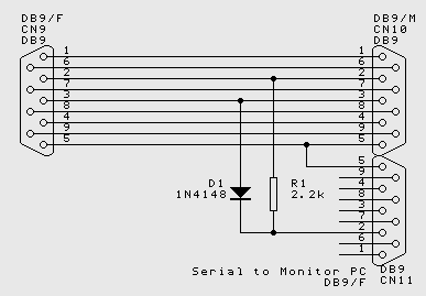
How to monitor RS232 Comms between two devices
$46 + shipping
There are three sockets on the T-Spy gadget. Two of them are connected straight through - plug them in series with the devices you wish to monitor - and the third goes off to a seperate PC for monitoring the communications.
The monitoring PC "Sees" on its serial port both sides of the serial conversation - that is it receives what is sent by the target PC and also what is sent by target peripheral. This can be a positive advantage, because the serial conversation can be observed as it progresses between the two devices. Some serial protocols, however, talk "full duplex" meaning that one end can start transmitting while it is still receiving from its peer. This unit cannot monitor full duplex Comms - the comms will be corrupted, gobble-dee-gook will be seen where the two transmissions overlap. The two sides of the conversation are wire-AND'ed, so Space or 0 overrides Mark or 1. But in addition the two sources are asynchronous, so reconstruction of a simultaneous conversation is not realistic.
This device is surprisingly successful in operation, and works to successfully record RS232 protocols for many different installs - mostly because many supposedly full duplex installations still talk half duplex in any case, because that is the sensible way to write the software. All in all, Not bad for one diode and a resistor...
- Contact Us
- Enquiry Form
- Sitemap
- The PCB design method
- About Circuit diagrams
- About PCB layout
- About Firmware design
- Spec'ing your job
- Our design service
- Example Projects Library
- Mechatronic control unit
- Garbage truck compactor
- RS232-RS485 convert (2006)
- Tone generator test project
- RS485 fire panel int.
- Front panel switches( A/D)
- Serial to IRDA
- Danfoss loop tester
- RAN Multilayer trainer
- Programmable Oscillator
- Pressure sense PCB
- Nursecall overdoor light V2
- Design step-by-step
- Circuit diagrams
- PCB Layout
- PCB Etching
- Prototyping
- Firmware design
- Documentation
- Manufacturing
- Economies of scale
- Test Procedures
- ECOs - changes
- EMI & ESD in design
- FR4 and fire resistance
- Project Specifications
- Specification Intro.
- Writing a Spec
- Tech Ingredients
- Example Specs (older)
- Selecting a designer
- R&D Economics
- Design Inspiration
- Autotrax Utitilities
- Autotrax links
- Our PicoBus IO Std
- RS232 connectors
- Our RS485 converter
- P89LPC932
- Our Program header
- How to use a Multimeter
- Our Site index
- Offsite Links (15000+)
- Google search
- Contact
©2013 AirBorn - Last updated 01 May 2013