Printed Circuit Board (PCB) Etching
The process of manufacturing the Printed Circuit Board laminate is handled by subcontractors. It is messy, time consuming, needs hundreds of square meters of space and few companies integrate it into their manufacturing process. It is a very interesting process to watch (well, if you enjoy visiting factories...) - we have some photos of an older PCB manufacturing plant. We outline the steps in the process below.
Local PCB Manufacture
We buy some PCBs in Australia, and have some PCBs made offshore. Whichever country you live in, it is likely that there are still local PCB manufacturers. Here in Australia most of the manufacturers send at least some of their work overseas - and many local companies are nothing but sales agents for China boards. If you have a local manufacturer, (vs the Sales agents) you should support them - they will provide you with a good service when the chips are down, so to speak. Perhaps economic pressure will mean some of your work needs to go offshore - but not all of it. PCB manufacture is very competitive in Asia, and prices will be lower compared with local product. However, there is a substantial cost involved in installing and servicing any electronics device that is many times higher than the cost of making the original PCB laminate. In practice, there is always room in the final product price, of atleast some of a companies products, to support your local manufacturers.
The PTH Printed Circuit board manufacturing process.
- CAD File processing
- The Gerber files (or PCB CAD files) are sent to the manufacturer by email
- The PCB manufacturer has their own pre-production inspection of the files at which time they add a drill list and identification
- The CAD files are rasterised and photoplotted to make film artwork
- Laminate drilling and electroplating
- The process starts with bare laminate material - usually FR-4
- The laminates, (with copper on both sides, but no pattern yet) are drilled with holes. For economy, the laminates are larger panels that often contain several PCBs
- The drilled laminates are coated in a chemical to enhance electroplating of holes. This is usually done using a multistep process called electroless copper.
- The laminates are put in a copper plating bath, all the holes are electroplated. This connects pads on opposite sides of the PCB, electrically, through copper in each hole.
- Laminate etching
- The laminates are coated with a UV-sensitive photo-resist
- The track pattern is imaged onto each side of each PCB, using the photoplots and UV light
- The photo-resist is developed, leaving photo-resist only where copper is required
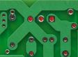
- The laminates are put in acid, to etch away unrequired copper, forming the track pattern
- The bare copper PCB, with tracks and pads now finished, is cleaned

- Laminate solder masking and tinning
- The bare copper PCB is silkscreened with a solder mask (usually green)
(Sometimes the solder mask is applied by photoimaging or dry film) - The solder mask is dried or cured
- The PCB is tinned or plated - solder, silver or gold is applied to exposed pads
- The PCB is levelled - bumps in the solder are made flat by using hot air (HASL)
- Final stages
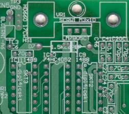
- The PCB is silkscreened with component Identification lettering (usually white)
- The silkscreen legend is dried or cured
- Any final drilling is done of holes that are not to be plated through, any routing is done, and the laminate is cut into individual printed circuit boards
The future - 3D printing?
An idea put forward recently is that PCB manufacture will be replaced by 3D printing. My opinion is that the scale of the task is wrong for this to happen in the near future. Right now the price of PCB manufacture for double sided work (offshore) is trending towards about $80 per square metre even in moderately small volumes. That is for a circuit board that has geometries of 8mil x 8 mil or less, thousands of holes, thru-hole vias, routing, soldermask, overlay.
We saw the advent of robotic assembly for surface mount (pick and place), but it is my opinion that traditional plate and etch lines will stay the standard production method for PCBs for some time to come - with the exposure and screen print steps becoming more automated - and so, more flexible. As a side note I would add that existing PCB milling is an alternative way to produce prototypes, although without PTH holes, and it is on the same individual scale as 3D printing - giving it a certain adventurous appeal.
- Contact Us
- Enquiry Form
- Sitemap
- The PCB design method
- About Circuit diagrams
- About PCB layout
- About Firmware design
- Spec'ing your job
- Our design service
- Example Projects Library
- Mechatronic control unit
- Garbage truck compactor
- RS232-RS485 convert (2006)
- Tone generator test project
- RS485 fire panel int.
- Front panel switches( A/D)
- Serial to IRDA
- Danfoss loop tester
- RAN Multilayer trainer
- Programmable Oscillator
- Pressure sense PCB
- Nursecall overdoor light V2
- Design step-by-step
- Circuit diagrams
- PCB Layout
- PCB Etching
- Prototyping
- Firmware design
- Documentation
- Manufacturing
- Economies of scale
- Test Procedures
- ECOs - changes
- EMI & ESD in design
- FR4 and fire resistance
- Project Specifications
- Specification Intro.
- Writing a Spec
- Tech Ingredients
- Example Specs (older)
- Selecting a designer
- R&D Economics
- Design Inspiration
- Autotrax Utitilities
- Autotrax links
- Our PicoBus IO Std
- RS232 connectors
- Our RS485 converter
- P89LPC932
- Our Program header
- How to use a Multimeter
- Our Site index
- Offsite Links (15000+)
- Google search
- Contact
©2013 AirBorn - Last updated 01 May 2013