AirBorn Electronics designs the controlling electronic PCB for your new product.
 Electronics Design

This page describes Electronics Development - the product design section of Research & Development. R & D is a bigger field than just this; it encompasses developing new techniques, totally new technologies, - pushing the boundaries. What we cover here is what is needed to use electronics to enable a new product to be built.
When designing any product, the first steps are to identify the need the product will fill and identify the market it will be sold into. This commercial groundwork is covered on the Writing a specification webpage.
This guide describes the basic process (used by most companies) for designing a new electronic product. The "Circuit - PCB - Prototype - Test" cycle yields working electronic prototypes. The design then goes on to beta testing, pilot run, and production release. In addition to the electronics work described, usually an industrial designer will be employed to produce the enclosure or case, with labelling and graphics.
There must be four ways to develop; this page describes the main "circuit-pcb-prototype" method. It does cost a reasonable amount of money, but is really quite versatile, and yields a production ready board design. The other methods are covered in brief on the Other methods webpage.
Nothing is particularly hard if you divide it into small jobs. --Henry Ford
The Specification
The Specification is the customer's instructions to the designer describing the features the new product should have. (See: More info - Specifications) A specification starts out as ideas and a wish list, then gradually gets nailed down to something more formal and explicit. It is a good idea to have a list of "reasons why" and "how it's done" to explain the specification, but keep these separate from the main document.
There is material on this website to help you: a guide to writing a specification for a new electronic product, help with specification construction, examples of specifications, and a glossary of technical information.
The basic, introduction explanation of the products function within a specification
should be quite short, keep it to one page:
One Page Principle: A specification that will not fit on one page of 8.5x11 inch
paper cannot be understood.
-- Mark Ardis
![]()
More detail on Specs: The Specification
The Circuit Design

The Circuit Diagram, also called the Schematic or Logic Diagram, maps out the electronics and connections in the most readily readable form. (See: More info - Circuit Design) The designer needs to do background work while producing the Circuit diagram, researching specifications of components, interaction between components (especially timing and loading) physical packages, and arrangement of connector pinouts. The circuit will often start on paper and finish in Computer Aided Design (CAD) format.
The finished circuit diagram, supported by notes if required, is the main reference document for the design.
More detail on Circuits: The Circuit Diagram
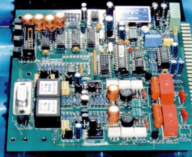
The Printed Circuit Board
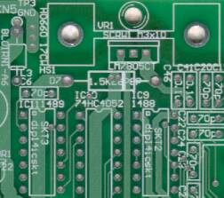
The Printed Circuit Board (PCB) is the laminate to which all the electronic components are soldered, with one or more layers of etched metal tracks making the connections.
- PCB Layout is the design of this base laminate (See: More info - PCB Layout)
- PCB Etching is the manufacture of this base laminate (See: More info - PCB Etching), and
- PCB Assembly is the final manufacture of the product - where all the components are soldered to the base laminate (See More info - PCB Assembly).
The Printed Circuit Board Layout

The connections between the components in the PCB Layout match the connections on the circuit diagram, and are physically placed and routed by the designer to get the best result. The PCB Layout defines the final physical form of the circuit, and enclosure and labelling details can be finalised as the layout is completed.
When the PCB layout is complete, the CAD file is translated to the RS274-X Gerber File format used by the subcontract PCB laminate manufacturer. (for detail on PCB laminate production see More info - PCB Etching) The manufacturer returns the etched PCB laminates 1-2 weeks later, ready for assembly into prototypes.
The trouble with doing something right the first time is that nobody appreciates
how difficult it was.
-- from "Fortunes" ![]()
More detail on PCBs: PCB Layout
Prototypes

It is worthwhile making 2 identical prototypes, rather than one. (See: More info - Prototypes) The Prototype circuitry is usually debugged in stages. The debugging proceeds according to the debug test procedure, if the designer was given time to write this in advance. Prototype microprocessor circuits are generally debugged with specially written diagnostic code, again progressing in stages.
When confidence has been gained in the operation of the prototype hardware, debug of the actual prototype program ("Firmware") will begin on the target.
More detail on Protoyping: Prototyping Electronics
Firmware
Software for the electronics is often 50% or more of the design work in a project. The programming that controls the microprocessor usually gives the electronic product its features and "glitz" whereas the hardware is the purely functional side of the equation.
The programming or coding for electronic products is usually written in 'C' or assembler, whereas the programming that runs on a PC will normally be written in C++, java or another language (and almost certainly not assembler). The programming for microcontrollers is totally different from that for a PC in any case - it is usually "more detailed" and less "generic" than the type of programming made for a personal computer, because it is more tightly coupled to the electronic hardware on which it runs, and because it usually has to respond more quickly - that is it has to run in "real time". There is usually a great deal of care and testing involved with programming for electronic products - while for some reason clients seem willing to accept bugs in windows software as somewhat normal, they are pretty unacceptable in, for example, the engine control unit for a car.
![]()
The firmware may be developed by a separate team, and it is at the prototype stage that the two projects come together. (See: More info - Firmware) When the two components are integrated and prototype testing is complete, the finished project is handed over to the customer.
Hofstadter's Law: It always takes longer than you expect, even when you take
Hofstadter's Law into account.![]()
More detail on Firmware: Software for Electronics
Pilot Run
To test the product further, a Pilot run normally follows the prototyping stage (See: More info - PCB Assembly). In the Pilot run, a small quantity of units (Perhaps 25) are field trialed in a beta test. The Pilot run is also an opportunity to assess the manufacturability of the design, and the useability of the documentation (see: more info - PCB Documentation).
It makes the manufacturers job easier to have a production sample available. Often one of the prototypes can be used as a production sample.
More detail on Production: PCB Assembly
Production
Following the pilot run there will likely be changes to the firmware, and possibly the circuit design, as the unit develops into a stable, final product. This process is controlled by ecos and version numbers. To put an electronics product into production (and for pilot run, also) the client needs the Gerber files, a good Bill Of Materials (BOM) with appropriate notes, and the firmware image. The client will get these from the Electronics designer, after they have paid for the completed work.
The technical documentation should be sufficiently detailed for a capable third party subcontractor to produce the boards. You should retain the services of your designer on a time and materials basis to support the design and to answer any questions asked by the board assembler.
The cost of the final production, and to some degree the style of design, is heavily influenced by the number of units manufactured (see Economies of scale).
More detail on Production: PCB Assembly
Innovation and Inspiration ... an opinion
For five seconds you're a genius, the rest of your life a bum.
Write it down.
-- Lawrence Miller
Inspiration - Why have we left this until last? We all know it has to come
first! The electronic design process can be methodical, almost mechanical, but the
 creativity at the start uses a very different set of human qualities.
Throughout the high-tech business world the most amazing success stories
are of inspired people, not large bureaucratic engineering departments
with efficient Total Quality Management. (No offence intended)
creativity at the start uses a very different set of human qualities.
Throughout the high-tech business world the most amazing success stories
are of inspired people, not large bureaucratic engineering departments
with efficient Total Quality Management. (No offence intended)
Creative aptitude is really important in making new technology products come to life, and also in identifying the market and the need the product will fill. The ability to bring that inspiration through into a final product requires the level-headed decision making. Some electronic designs are not really new products as such, but developments of existing products. These designs, also, require creative vision to see which new features are really the most desirable, and how the design can be economically produced.
Bring in ideas and entertain them royally,
for one of them may be king.
--Mark Van Doren
- Contact Us
- Enquiry Form
- Sitemap
- The PCB design method
- About Circuit diagrams
- About PCB layout
- About Firmware design
- Spec'ing your job
- Our design service
- Example Projects Library
- Mechatronic control unit
- Garbage truck compactor
- RS232-RS485 convert (2006)
- Tone generator test project
- RS485 fire panel int.
- Front panel switches( A/D)
- Serial to IRDA
- Danfoss loop tester
- RAN Multilayer trainer
- Programmable Oscillator
- Pressure sense PCB
- Nursecall overdoor light V2
- Design step-by-step
- Circuit diagrams
- PCB Layout
- PCB Etching
- Prototyping
- Firmware design
- Documentation
- Manufacturing
- Economies of scale
- Test Procedures
- ECOs - changes
- EMI & ESD in design
- FR4 and fire resistance
- Project Specifications
- Specification Intro.
- Writing a Spec
- Tech Ingredients
- Example Specs (older)
- Selecting a designer
- R&D Economics
- Design Inspiration
- Autotrax CAD (any OS)
- Autotrax Utitilities
- Autotrax links
- Our PicoBus IO Std
- RS232 connectors
- Our RS485 converter
- P89LPC932
- Our Program header
- How to use a Multimeter
- Our Site index
- Offsite Links (15000+)
- Google search
- Contact
©2013 AirBorn - Last updated 18 April 2013